For businesses relying on reliable electrical systems, ensuring safety and functionality is paramount. Regular evaluation and maintenance of grounding systems are pivotal in commercial electrical services.
Bonding and grounding serve as effective methods to reduce static electricity ignition risks.
A bonding system links conductive equipment and structures, maintaining a uniform potential to prevent static sparking.
Grounding, a specialized bonding, connects conductive equipment to the facility's grounding system, averting sparking between conductive equipment and ground.
In areas prone to flammability risks, it's essential to bond conductive items separated from the ground by nonconductors like hoses, supports, or gaskets.
Isolated conductive objects can accumulate charges, leading to static sparks. These objects include screens, nonconductive drum rims, probes, and high-pressure cleaning gear.
Interconnected grounding systems, including supplementary electrodes, are vital for consistent ground potential across materials and containers. Bonding conductors should be durable and low-resistance, ensuring direct and secure connections.
When installing static grounding systems, avoid using electrical-current-carrying systems as grounds, preventing potential fires caused by improper connections. Neutrals within the electrical system must only be integrated into the ground system at specified common bonding points or service entrances.
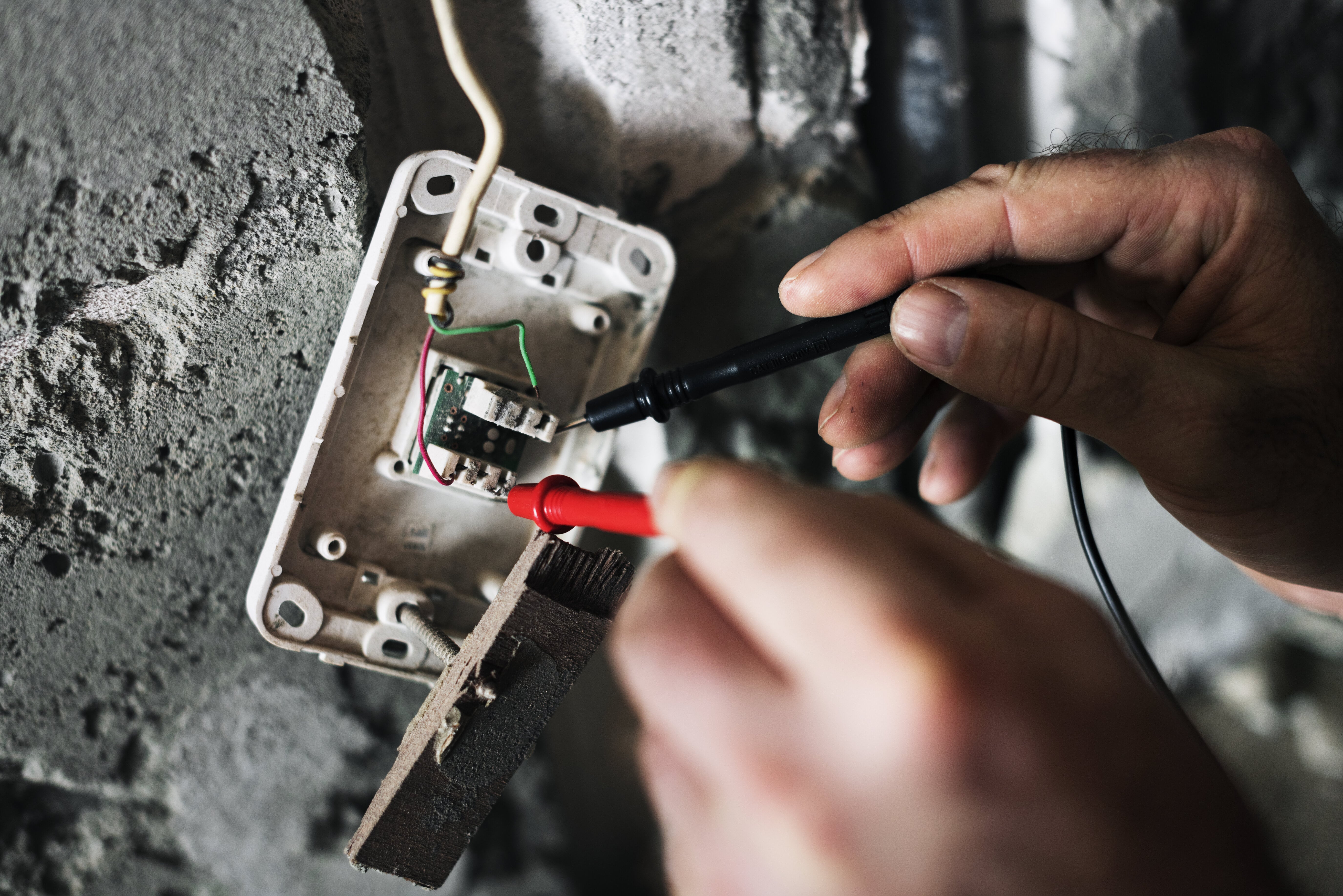
Ensuring the correct setup of bonding and grounding devices is crucial for safeguarding personnel and equipment. During installation, a resistance test is imperative to confirm proper electrical continuity to the ground. Regular inspections and maintenance programs are essential to guarantee this continuity remains intact throughout the system.
Maintenance aspects for bonding and grounding fall into three primary categories. The first involves point-type clamps with flexible leads to temporarily bond portable containers to the facility's grounding system.
Next, fixed grounding conductors and busbars establish connections between flexible leads and fixed equipment, ensuring a secure link to the ground.
Lastly, the facility grounding system is crucial, providing a stable ground connection for the entire setup.
Flexible leads are prone to mechanical damage, corrosion, and wear and should be uninsulated for frequent inspection. Assessments should evaluate the cleanliness and sharpness of clamp points, stiffness of clamp springs, conductor integrity, and connection quality.
An approved ohmmeter should be used regularly to test electrical resistance and continuity for a more comprehensive assessment. Attach one lead to a clean container spot and the other to the facility grounding system. The measured resistance should ideally be under 25 ohms, typically around 1 ohm. Shake the leads to ensure sound contact, avoiding reliance on contact through dirt or rust.
Fixed leads and busbars typically face minimal damage but should undergo annual ohmmeter checks. They should be tested between the leads or bus and the facility ground, aiming for a measured resistance of less than 1 ohm.
Regular checks for conductive hoses, especially after repairs, are crucial. Conductive segments might break or be inadequately repaired. Non-conductive hoses with internal spiral conductors should ensure the spiral conductor contacts adjacent metallic fittings and hose shaking aids in accurate measurements.
The facility ground system is the last element of the static bonding and grounding system. This system needs to comply with the NEC regulations. Underground piping that has cathodic protection should not serve as the grounding system.
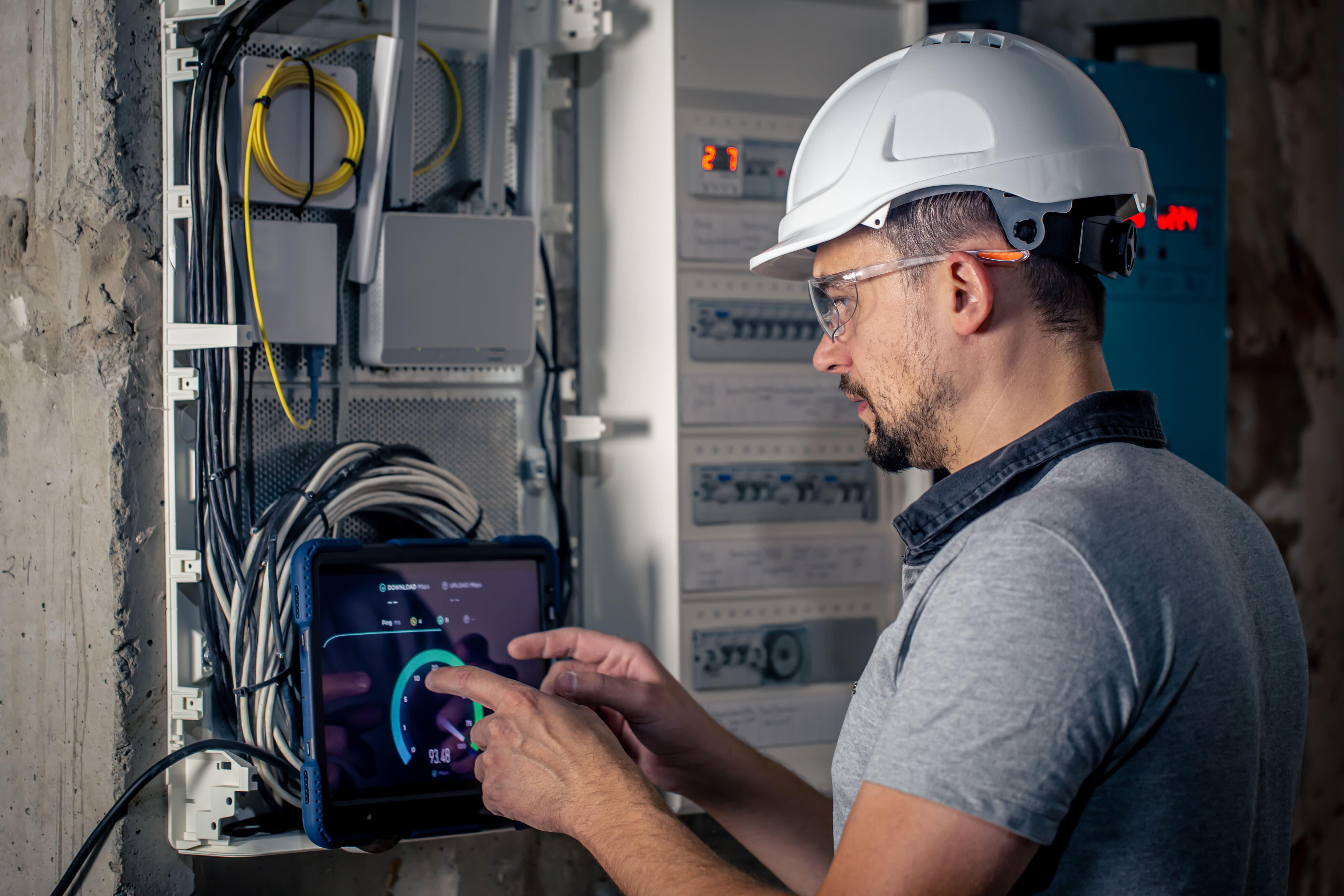
Testing the ground in electrical systems serves as a crucial safety measure, ensuring circuits have a secure path to divert excess electricity to the ground in case of an unplanned electrical contact. This test evaluates the circuit's performance, ensuring it meets safety standards.
Ground testing serves two essential purposes—during facility construction and as routine checks to ensure optimal system performance.
This practice holds immense importance for various reasons:
Before embarking on testing a ground circuit, several crucial elements require understanding:
Utilize dedicated ground testers or instruments designed explicitly for ground testing purposes.
Comprehend the test procedures and acquaint yourself with the tools and their operational functions.
Measure the complete area surrounding the electrode, a pivotal aspect for accurate performance assessment.
Ensure proper placement of probes concerning buried objects, moisture pockets, and other relevant factors.
Various agencies and organizations issue guidelines and standards for ensuring grounding safety. Regardless of the guidelines followed, certain key elements remain consistent, such as inspecting ground connections and stakes annually for issues like corrosion, which can elevate resistance.
Four commonly used methods for testing ground resistance include:
This method is frequently used for newly installed grounding systems due to the soil's diverse layers, leading to varying resistance. Conducting soil resistivity involves using a ground resistance tester.
Aside from the soil profile, numerous factors can influence the local resistivity of the soil. Conducting a comprehensive study of the area and establishing an area profile is crucial to ensure appropriate configuration. Achieving this requires conducting multiple soil resistivity tests, placing the stakes in various directions and depths, and examining resistivity levels at different intervals.
The fall-of-potential method is a common approach used to evaluate the effectiveness of individual grounding stakes or entire grounding systems in dissipating electrical energy.
Disconnect the stake under test from the system, designating it as the earth electrode.
Connect the testing apparatus to the earth electrode and two additional stakes, known as the outer and inner stakes, positioned in line with the earth electrode.
Using the ground tester, apply a known current through the outer stake and earth electrode.
The distance between the outer and inner stakes is determined by the length of the electrodes, typically guided by charts or manuals for proper installation.
Employing the stakeless technique for testing ground resistance eliminates the hazards associated with disconnecting electrodes and negates the need to seek suitable test-stake locations.
Stakeless testing offers unparalleled convenience, adaptable for use in various locations.
Clamps are positioned near the connecting cable or earth electrode for setup.
A known current is introduced through one clamp and measured at the other end.
The ground tester computes the loop resistance of the ground earth. Nonetheless, if only one available path allows electricity to flow to the ground, stakeless testing may not be viable.
The selective method for ground testing shares similarities with the fall-of-potential test but presents enhanced safety measures by eliminating the need to disconnect the earth electrode from the site.
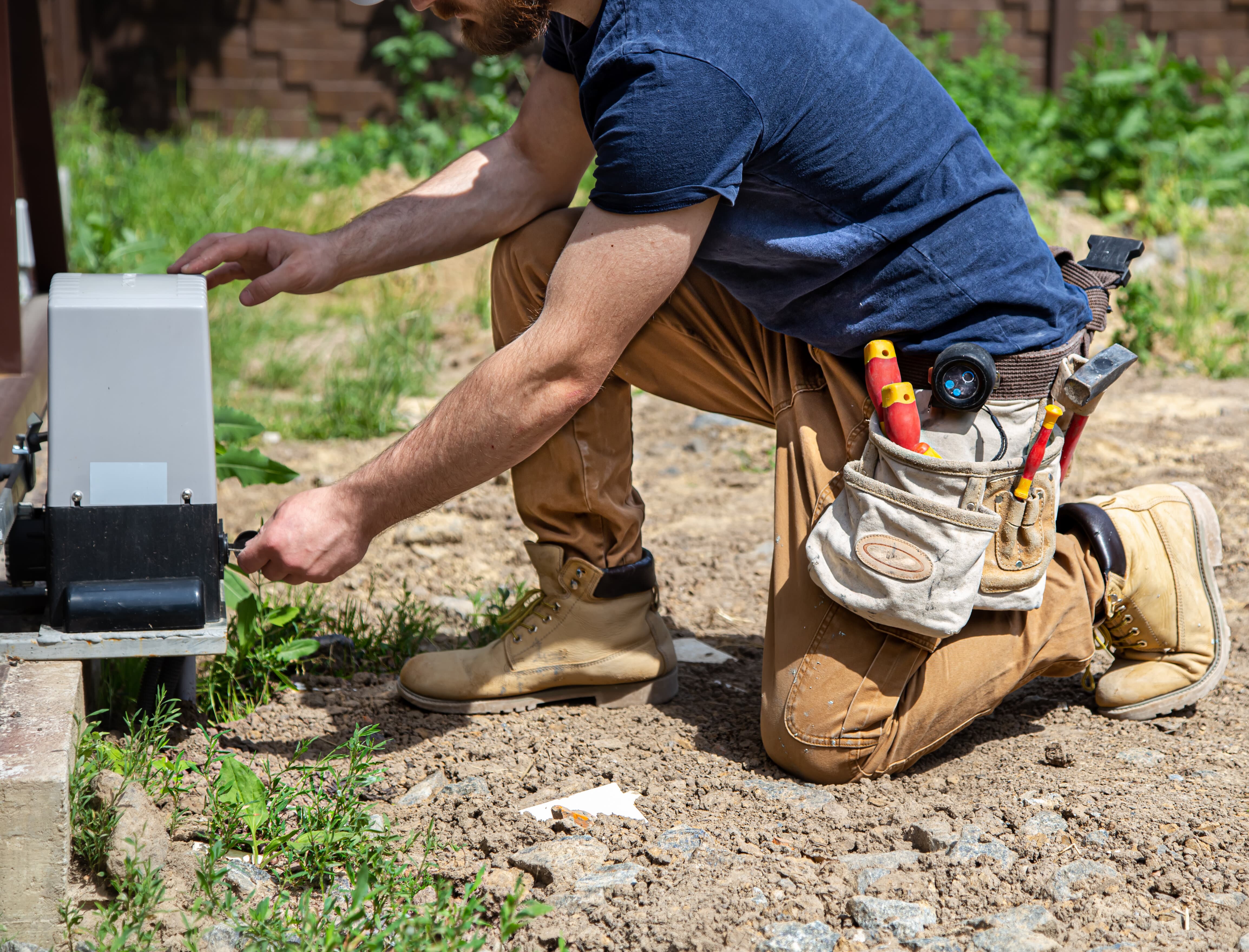
Proper electrical grounding plays a critical role in safeguarding equipment and lives. Ensuring its effectiveness through regular checks is imperative. Even the most robust grounding system bonding will only be effective if it can achieve a low-impedance ground stake, underscoring the significance of comprehensive ground testing procedures.
Verifying the impedance of grounding electrodes in commercial, industrial, and residential structures is integral to their electrical safety measures. These systems are designed to provide a secure path for excess current, such as during lightning strikes or voltage surges, directing it safely into the earth. A ground electrode establishes this connection between the electrical system and the earth.
Various electrical codes and engineering standards outline minimum impedance requirements for the ground electrode to guarantee a dependable link to the Earth. The International Electrical Testing Association recommends testing ground electrodes for systems in good condition every three years with standard up-time requirements.
This informative note delves into the fundamentals of earth/ground principles and safety considerations before detailing key testing methods, including 3 and 4-pole Fall of Potential testing, selective testing, stakeless testing, and 2-pole testing.
The grounding of a facility serves two primary purposes as outlined by the US National Electrical Code (NEC):
Current naturally follows the path of least resistance back to its source, whether it's a utility transformer, a facility's internal transformer, or a generator. On the other hand, lightning always seeks a path to reach the earth.
During a lightning strike, a low-impedance ground electrode efficiently channels the energy into the earth. This is achieved through grounding and bonding systems that link the earth near the building with its electrical system and steel framework. Maintaining a low potential gradient minimizes potential damage by ensuring the facility remains at approximately the same potential during a lightning event.
In the case of contact between a medium voltage utility line (over 1000V) and a low voltage line, nearby facilities could face drastic overvoltage. A low-impedance electrode helps curtail this voltage increase. A low-impedance ground can also offer a return path for transient events generated by the utility.
Ground electrode impedance is influenced by two main factors: the surrounding earth's resistivity and the electrode's construction. The resistivity of the earth is complex due to various factors like soil composition, mineral content, temperature changes, settling, and buried structures like metal tanks or pipes.
To lower earth impedance, driving an electrode deeper is a common strategy. Other methods include using arrays of rods, conductive rings, or grids to increase the electrode's effective area. Proper spacing between multiple rods outside each other's "influence areas" is crucial for maximum effectiveness. Standards such as the NEC and IEEE recommend specific limits for electrode impedance, but local authorities and plant managers ultimately determine acceptable thresholds.
Note: While ground testers measure impedance using alternating current at power line frequencies, the resistive component of earth impedance typically overshadows the reactive component, leading to the interchangeable use of terms like impedance and resistance.
Grounding testing frequency is a crucial consideration in ensuring electrical safety. Industry standards typically advocate for an annual examination of protective grounds.
Standards for ground testing are outlined by the National Fire Protection Association (NFPA) and Institute of Electrical and Electronics Engineers (IEEE), which recommend a ground resistance value of 5.0 ohms or less. While zero ohms is the ideal value for ground resistance, achieving this is often unfeasible.
To test for proper grounding, confirm power in a 3-slot outlet and check for a faulty ground connection. A reliable test involves removing the probe from the neutral slot and touching it to the center screw on the cover plate. The tester should indicate a proper ground connection by lighting up.
According to the National Electrical Code, grounding electrodes must resist ground not exceeding 25 ohms. In cases where resistance surpasses this threshold, using two or more electrodes connected in parallel is recommended. These electrodes should be at least six feet apart to comply with regulations.
Understanding the intricate dynamics of grounding and bonding systems is crucial for safeguarding your facilities against potential electrical hazards. Whether it's ensuring a low-impedance ground electrode during a lightning strike or meeting the recommended ground resistance values outlined by industry standards, our team at Helping Hands Electric is committed to your electrical safety.
With a wealth of knowledge in the field and a dedication to adhering to the highest standards, we provide comprehensive electrical solutions. From annual grounding examinations to addressing specific electrical needs, we're here to help you navigate the complexities of electrical systems. Contact Helping Hands Electric for all your current and future commercial electrical services, ensuring a secure and reliable electrical infrastructure for your facilities.
